Turboshaft Engine, with Radial Compressor and Turbine


$10.00 Turboshaft Engine, with Radial Compressor and Turbine
Published 2018-09-24T13:10:17+00:00
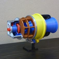
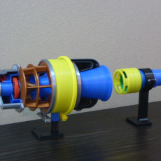
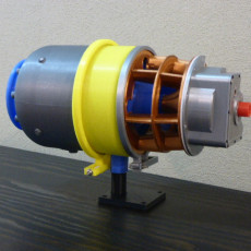
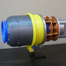
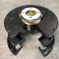
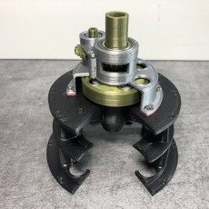
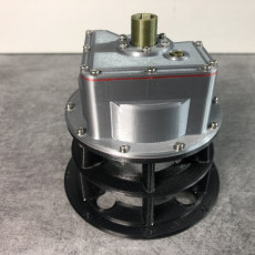
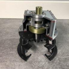
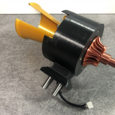
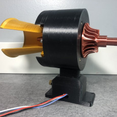
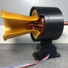
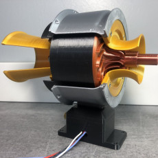
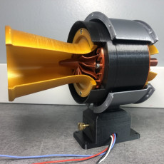
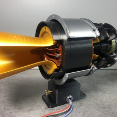
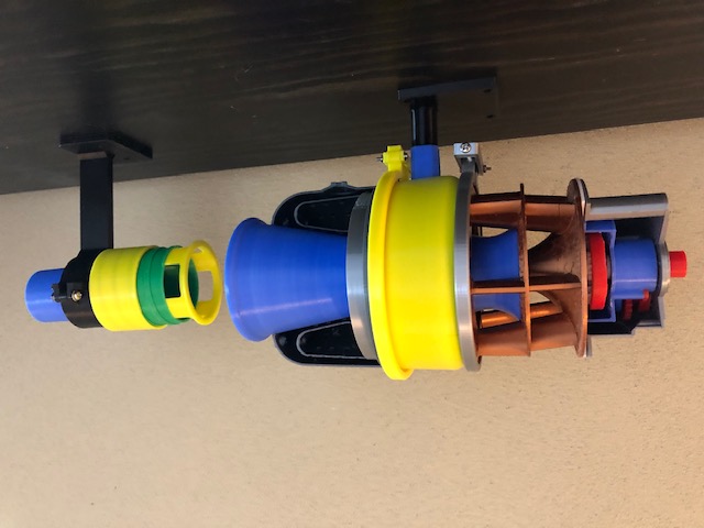
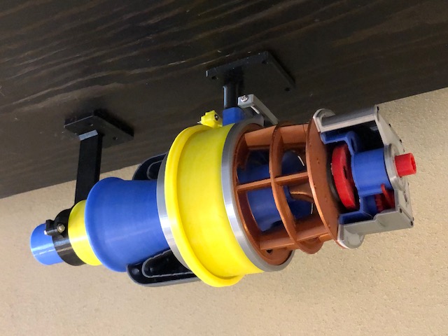
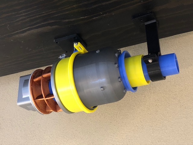
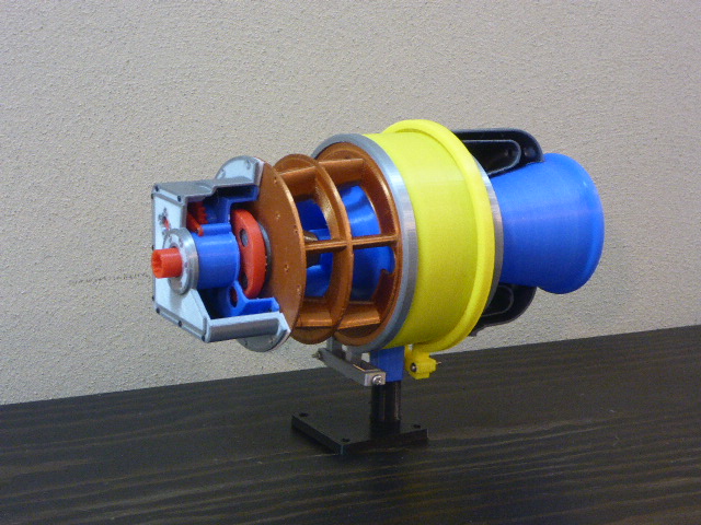
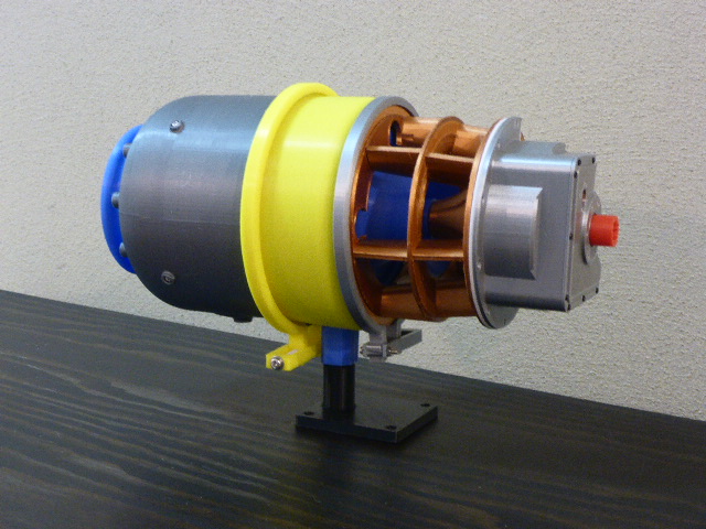
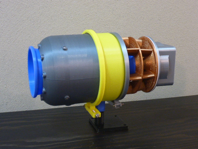
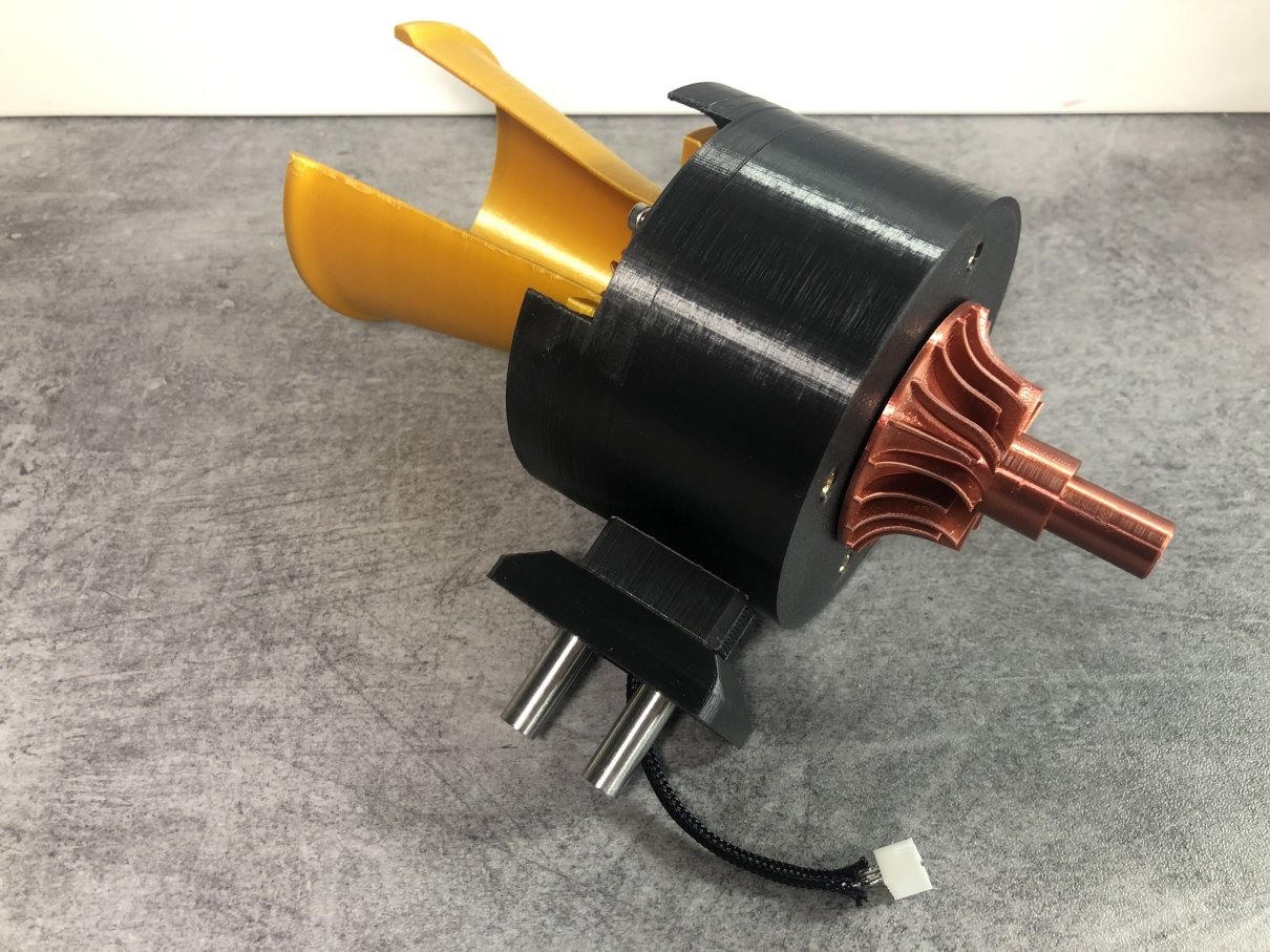
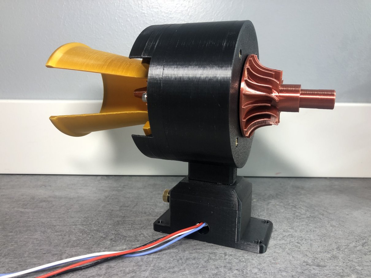
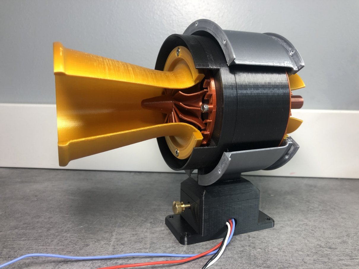
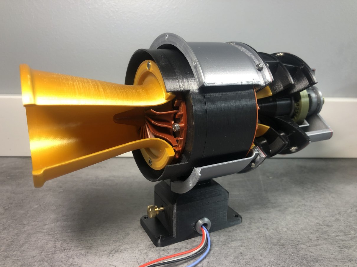
This model is a turboshaft engine which uses a radial compressor and a radial turbine.
It is a type mainly used for compact engines. Example: APU (auxiliary power unit) etc.
This was created in order to use for the source of a shaft horsepower for turning other models (for example, main-gear box for helicopters, etc.) besides only explaining a structural aspect.
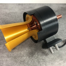
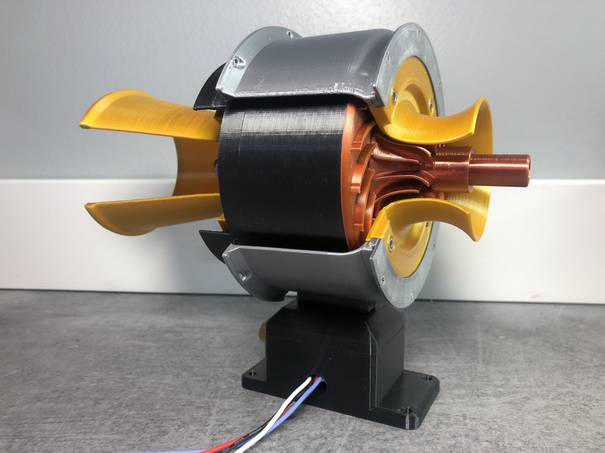
A home vacuum cleaner is used as the source of power of this model.
The features are as follows.
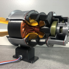
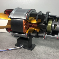
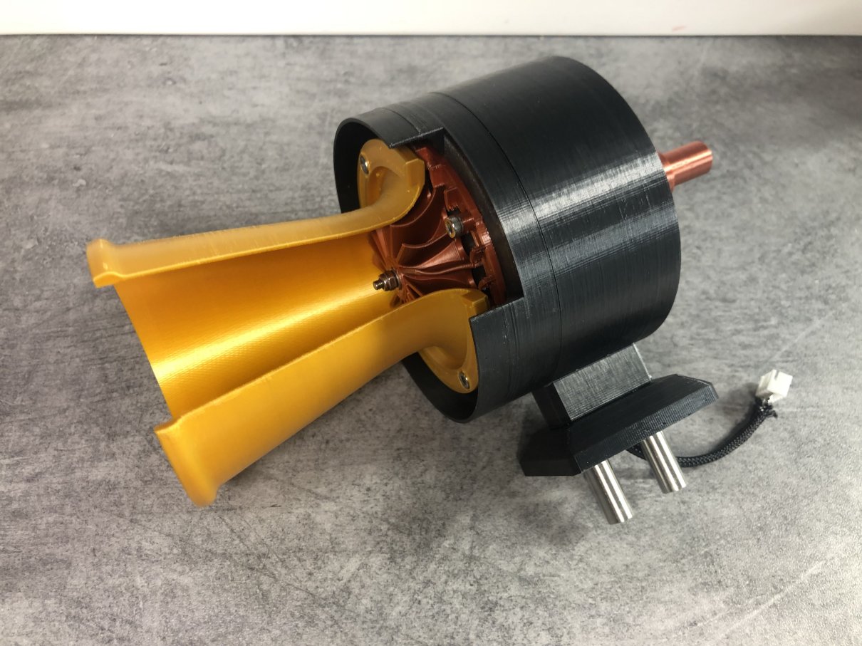
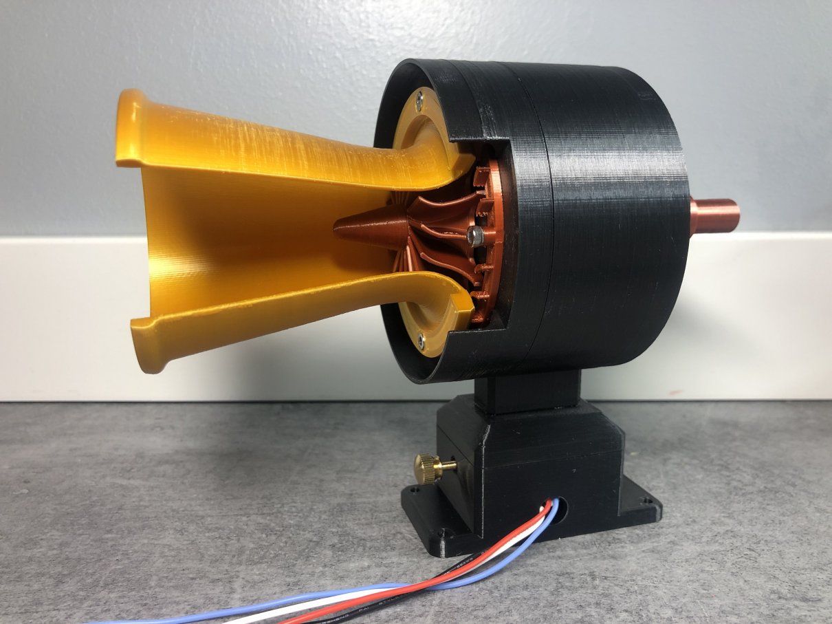
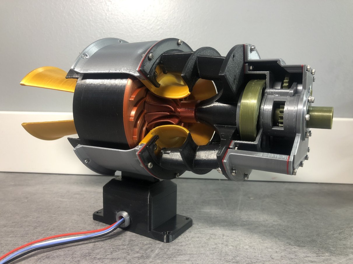
① Radial compressor (Impeller), Diffuser
② Radial turbine rotor, Turbine nozzle
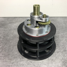
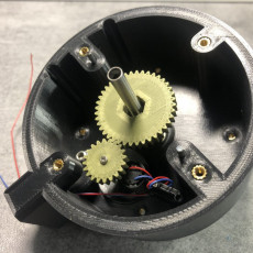
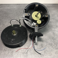
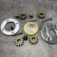
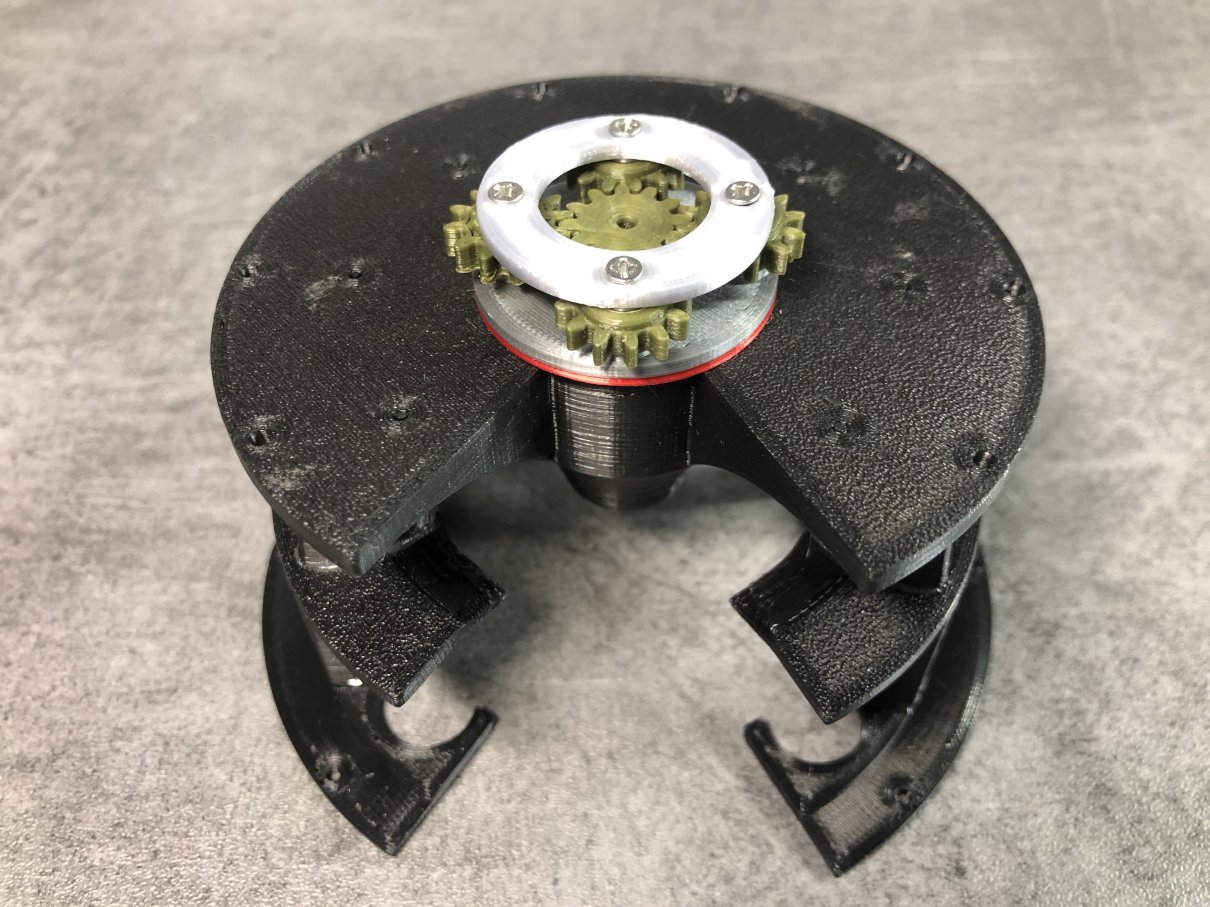
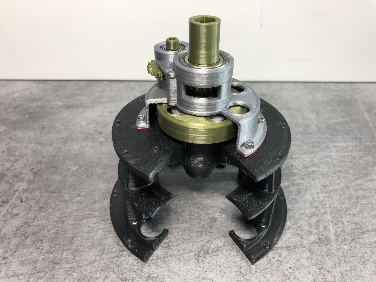
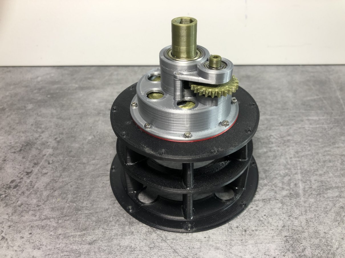
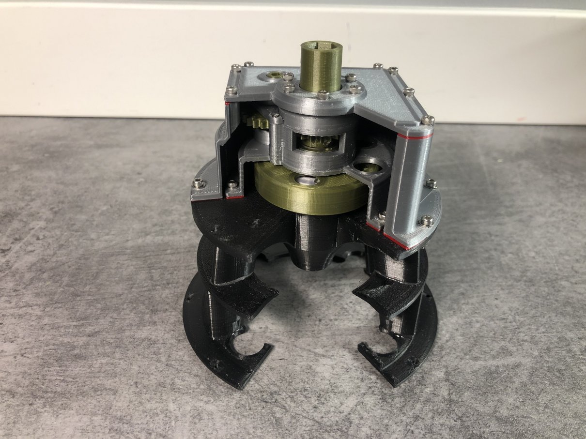
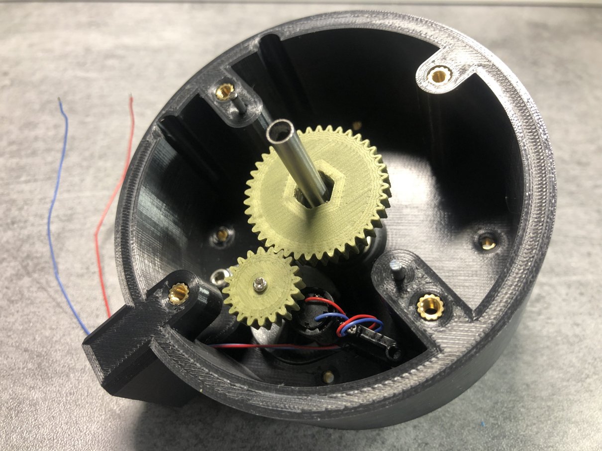
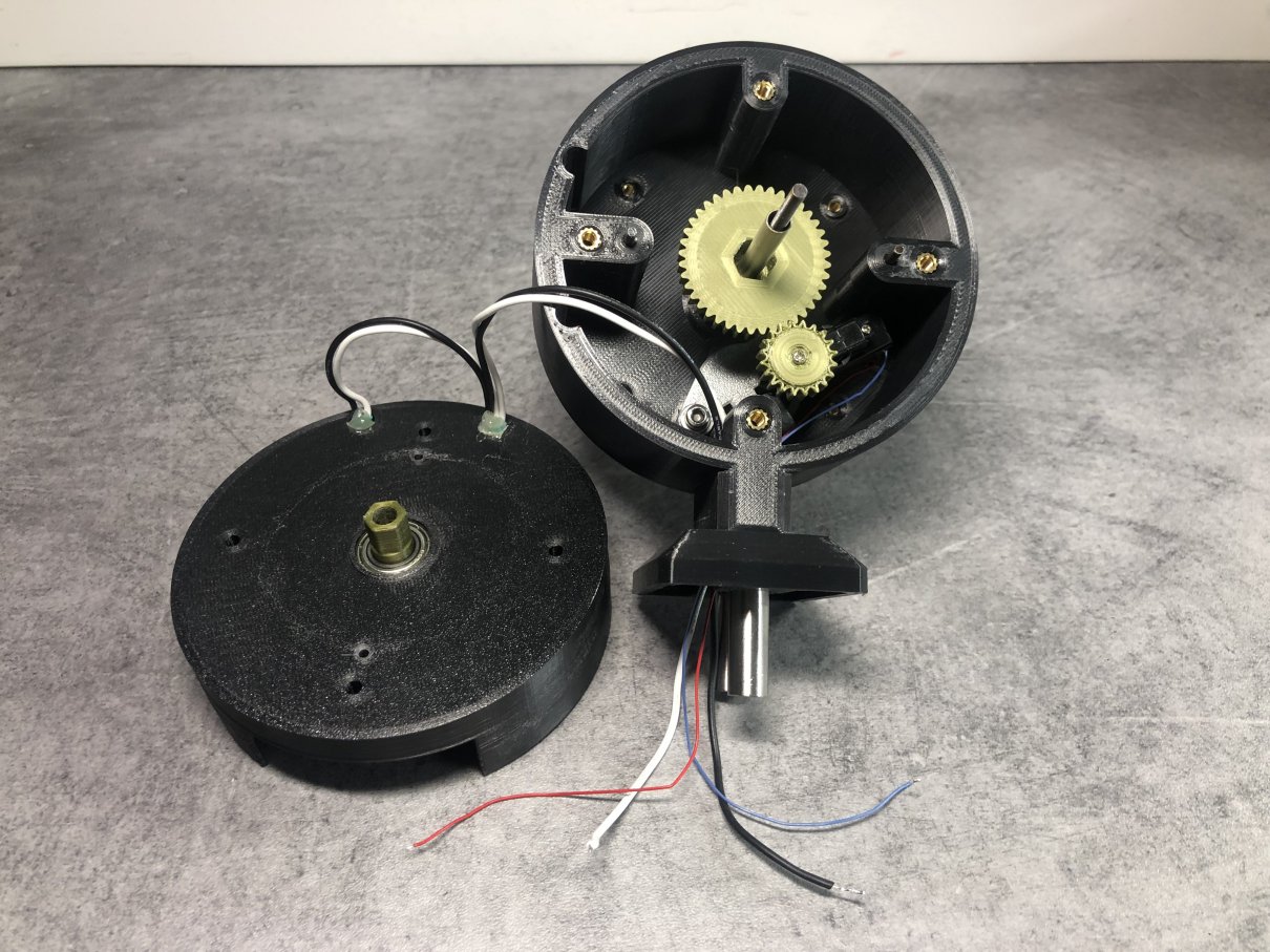
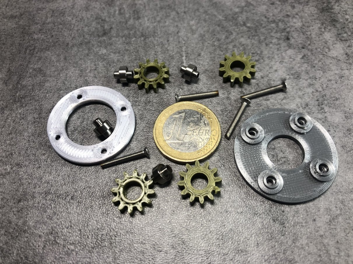
③ Planetary reduction gears
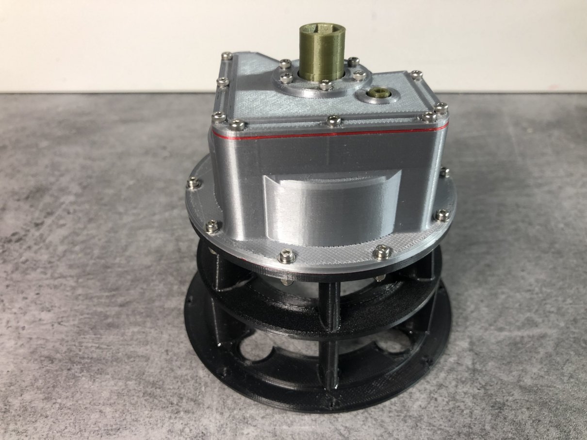
④ Output shaft
⑤ Use metal ball bearings for all the rotating shafts.
⑥ Prepare the parts for reversing rotating direction.
⑦ In order to disassemble easily, introduce the clamp system and the finger screw.
⑧ The vacuum nozzle with the variable opening for speed control.
Since it rotates well beyond anticipation, it can use as the source of power.
But, the maximum allowable RPM and torque are not verified.
Please decide by self-responsibility.
Video: https://youtu.be/maxeQ6HPnNI
B. Assembly Manual (PDF format, total 20 pages)
The detail assembly manual including "Parts-List", "After printing treatment" and "Assembly procedure" are prepared based on "Standard Skill (Filing, Drilling, Tapping and painting)".
In order to make it rotate smoothly, careful eccentricity and gap adjustment are needed.
C. General Notes
1. Bearing
Metal Ball Bearing are used for every shafts. Refer to Appendix.
2. For M1.4 Screw
No need “Tapping”. Drill with φ1.0 drill then direct screw-in.
3. STL file
“ws” of last 2 digits of file name means “With Support” special designed.
Total STL files are 48 items including the optional items. (Vacuum Duct, Stand etc.)
4. Blending of the gear tooth profile is important to get smooth rotation.
5. For the Helicopter Power Train, use the following parts as a set.
- Comp-Diffuser01CCW
- Impeller01CCW
- Turb-Nozzle101CCW
- Turbine101CCW
Total Net Print Time: Approx. 72HR
- (Estimated as case of PLA, 0.4mm Nozzle, 0.2mm Layer Height, 40% infill and No raft and support)
Especially, Air-Intake-Case201mws.stl needs about 12 hours to print.
Note: When at actual print, each parameter may be adjusted by your experience.
3D printing settings
Raft, Support, Layer Height, Infill: Depending on your experience.
But the parts having gear, small shaft and thin portion: 100% infill is recommended.
My models were printed by "idbox" using with 0.4 nozzle, 1.75 PLA.
[Update] 2019.05.07 gear-carrier102.stl changed.
2019.05.09 Assy-Manual typo revised.
2019.06.29 Gear-BRG-Hsg301ws.stl added.
2019.07.02 VC-Duct-Sprt01.stl, VC-Duct-Sprt02.stl added.
2019.08.20 Note C.5 added. Optional "Air-Intake-Case301ws" (with my special support) added.
2020.07.24 "Air-Intake-Case201.stl" (No support version) added for reference.
2020.07.27 Image "Air Intake Case Designs" is added.
2020.08.14 Figure "Selective Parts for Engine Rotating Direction" is added.
I do hope your success!!
See above
| Date published | 24/09/2018 |
| Price | $10.00 |
| Tecnologia | FDM |
| Complessità | Easy |

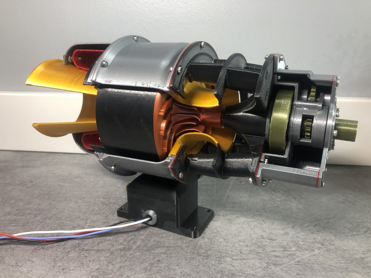
Turboshaft Engine with Radial Compressor. It will be followed by Main Gear Box, Main Rotor Head, and Control Sicks, all for Helicopter.